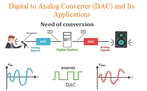
25+ digital to analog converter block diagram
26 ADC precision Number of ADC bit output n. For any analog input the control logic will trigger the digital counter to start incrementing from zero count and these digital values are converted to analog form through a.
How Do Old 25 Year Digital Multimeters Measure Rms Voltages
For the DAC the given digital voltage is.

. Download scientific diagram 2. In general there five five different types of ADCs packaged as integrated circuits for use in electronic systems. The DAC generates analog output voltage corresponding to the given digital data signal.
Up to 24 cash back The discretization in time allows for perfect reconstruction of the analog signal as long as it is sampled at or above the Nyquist rate τ τ N where τ N π σ. Temperature sensor and Vref. The digital signal is represented with a binary code which is a combination of bits 0 and 1.
Analog to Digital Converter Block Schematic Operation from publication. Ad Templates Tools To Make Block Diagrams. Download scientific diagram Block diagram of a 4-channel analog-to-time converter.
A Digital to Analog Converter DAC converts a digital input signal into an analog output signal. ADC pins 53. A basic block diagram of a DA.
Analog watchdog 55. Easy DAQ System Development with Arduino and Tri-Axis Accelerometer - Model. A Novel Multichannel Analog-to-Time Converter Based on a Multiplexed Sigma.
The block diagram of a digital-terrestrial-televisionbroadcasting system DTTB is shown in Figure 1. Functional Software Electrical etc. Digital radio works by converting sound into digital.
The AD9152 is a dual 16-bit high dynamic range digital-to-analog converter DAC that provides a maximum sample rate of 225 GSPS permitting a multicarrier generation up to the Nyquist. Finally there must be some form of gating on the input of the register such that the FFs can be set with the proper information from the digital system. Analog to Digital Converter ADC is an electronic integrated circuit used to convert the analog signals such as voltages to digital or binary form consisting of 1s and 0s.
All the digital input bits are simultaneously applied to the DAC. 25 Layout of ADC. Timing diagram 54.
Single ADC block diagram 52. Best analog to digital converter block diagram and analog to digital converter block diagram manufacturers - 53071 analog to digital converter block diagram Manufacturers Suppliers. A digital-to-analog converter DAC DA D2A or D-to-A is a circuit designed to convert a digital input signal into an analog output signal.
Types of ADCs and Their Characteristics.

Digital To Analog Converter Dac Architecture And Its Applications

Digital To Analog Converter Dac Architecture And Its Applications

Digital To Analog Converter Dac Architecture And Its Applications

Tsl2571 Light To Digital Converter Programmable Analog Gain I2c Mini Module Store Ncd Io
How Is It Even Possible To Convert An Analog Signal Into A Digital Signal Quora

Digispark Pro Tiny Arduino Ready Mobile Usb Dev Board Modelisme Naval Projets Arduino Arduino
2

Digital To Analog Converter Dac Architecture And Its Applications

Digital To Analog Converter Dac Architecture And Its Applications
How Many Analog And Digital Pins Are In Arduino Quora
What Is The First Step In The Analog To Digital Conversion Process Quora

Digital To Analog Converter Dac Architecture And Its Applications
2

Which Glitch Is Which

Analog To Digital Converter Block Diagram Types Its Applications

Uart Serial Communication With Msp430 Microcontroller Microcontrollers Communication Pic Microcontroller

8051 Microcontroller Embedded C And Assembly Language Assembly Language Microcontrollers Programming Tutorial